SOLVED Issues with RAW-MIPI-SC132M on Jetson Nano Dev Kit
-
Hi. I'm trying to make my RAW-MIPI-SC132M work on Jetson Nano Dev Kit. I am following the instructions on the wiki https://wiki.veye.cc/index.php/Mv_series_camera_appnotes_4_jetson
I enter the following commands:
v4l2-ctl -d /dev/video0 --set-ctrl roi_x=0
v4l2-ctl -d /dev/video0 --set-ctrl roi_y=0
v4l2-ctl -d /dev/video0 --set-ctrl preferred_stride=1088
v4l2-ctl -d /dev/video0 --set-fmt-video=width=1080,height=1280,pixelformat=GREY --stream-mmap --stream-count=-1 --stream-to=/dev/null
The last command stuck and nothing happens. At this moment the following entries appear in dmesg:
[ 3896.073092] mvcam 7-003b: csi2_try format
[ 3896.073100] mvcam 7-003b: mvcam_csi2_get_fmt_idx_by_code success
[ 3896.161233] mvcam 7-003b: camera_common_mclk_enable: no device power rail
[ 3896.671039] vi 54080000.vi: Calibrate csi port 0
[ 3896.672606] mvcam 7-003b: camera_common_mclk_disable: no device power rail
[ 3896.680473] mvcam 8-003b: camera_common_mclk_enable: no device power rail
[ 3897.192654] vi 54080000.vi: Calibrate csi port 4
[ 3897.194907] mvcam 8-003b: camera_common_mclk_disable: no device power rail
[ 3897.202591] mvcam 7-003b: camera_common_mclk_enable: no device power rail
[ 3897.722337] vi 54080000.vi: cil_settingtime was autocalculated
[ 3897.722348] vi 54080000.vi: csi clock settle time: 13, cil settle time: 10
[ 3897.728526] vi 54080000.vi: tegra_channel_error_status:error 4000 frame 0
[ 3897.736817] vi 54080000.vi: tegra_channel_error_status:error 4000 frame 1
[ 3897.745104] vi 54080000.vi: tegra_channel_error_status:error 4000 frame 2
[ 3897.753514] vi 54080000.vi: tegra_channel_error_status:error 4000 frame 3
.....
[ 3901.245010] vi 54080000.vi: tegra_channel_error_status:error 4000 frame 414
[ 3901.253394] vi 54080000.vi: tegra_channel_error_status:error 4000 frame 415
[ 3901.261730] vi 54080000.vi: tegra_channel_error_status:error 4000 frame 416
[ 3901.269192] mvcam 7-003b: camera_common_mclk_disable: no device power rail
My setup:
- Jetson Nano Dev Kit B00 (tegra210-p3448-0000-p3449-0000-b00)
- JetPack 4.6.3, L4T 32.7.3
- Kernel binary image from nvidia_jetson_veye_bsp (Image_l4t_r32.7.3_veyecam.tar.gz)
- Device tree from nvidia_jetson_veye_bsp (dtbs/Nano/JetPack_4.6.3_Linux_JETSON_NANO_TARGETS/dts dtb/MV-MIPI-MVCAM/tegra210-p3448-0000-p3449-0000-b00.dtb)
user@nano:~$ dmesg | grep mvcam
[    1.936838] mvcam 7-003b: veye mv series camera driver version: 01.01.03
[    2.438363] mvcam 7-003b: camera is: RAW-MIPI-SC132M
[    2.438724] mvcam 7-003b: firmware version: 0x1040000
[    2.445012] mvcam 8-003b: veye mv series camera driver version: 01.01.03
[    2.946454] mvcam 8-003b: camera is: RAW-MIPI-SC132M
[    2.946805] mvcam 8-003b: firmware version: 0x1040000
[    3.128582] vi 54080000.vi: subdev mvcam 7-003b bound
[    3.129269] vi 54080000.vi: subdev mvcam 8-003b bound
...
user@nano:~/i2c_tools$ ./mv_mipi_i2c.sh -b 7 -r -f trgmode
r trigger mode is 0
user@nano:~/i2c_tools$ ./mv_mipi_i2c.sh -b 7 -r -f roi
r roi is 0,0,1024,1280
user@nano:~/i2c_tools$ ./mv_mipi_i2c.sh -b 7 -r -f maxfps
r maxfps @ current setting is 120.00 fps
user@nano:~/i2c_tools$ ./mv_mipi_i2c.sh -b 7 -r -f fps
r fps is 120.00 fps
user@nano:~/i2c_tools$ ./mv_mipi_i2c.sh -b 7 -r -f pixelformat
r pixelformat is 0
What is the correct way to capture images from the camera?
-
@antony
Please try qv4l2 first.sudo apt install qv4l2qv4l2 -d /dev/video0 qv4l2 -d /dev/video1Then press preview button.
-
Unfortunately this didn't help. The application shows a black screen, dmesg shows the same messages. I tried both cameras.
What else can I try?
-
@antony
I have not encountered this error message before. Can you take a picture of your hardware connections and I'll take a look?tegra_channel_error_status:error 4000 frame 0 -
Connections looks correct.

The following messages bother me
[ 3897.194907] mvcam 8-003b: camera_common_mclk_disable: no device power rail -
I also connected the camera module to the Raspberry Pi according to the instructions on the page https://wiki.veye.cc/index.php/Mv_series_camera_appnotes_4_rpi
To test the camera I used the following commands:
user@raspberrypi:~ $ sudo dmesg | grep mvcam
[    0.068850] platform fe801000.csi: Fixed dependency cycle(s) with /soc/i2c0mux/i2c@1/veyemvcam@3b
[   11.272390] veye_mvcam: loading out-of-tree module taints kernel.
[   11.273159] mvcam 10-003b: veye mv series camera driver version: 01.01.04
[   11.278750] mvcam 10-003b: Unable to load veye_vbyone driver,will go on
[   11.783067] mvcam 10-003b: camera is: RAW-MIPI-SC132M
[   11.784948] mvcam 10-003b: firmware version: 0x1040000
[   11.812785] mvcam 10-003b: mvcam_enum_controls success
[   11.814170] mvcam 10-003b: Consider updating driver mvcam to match on endpoint
user@raspberrypi:~ $
user@raspberrypi:~ $ v4l2-ctl --set-ctrl trigger_mode=0
user@raspberrypi:~ $ v4l2-ctl --set-ctrl trigger_src=0
user@raspberrypi:~ $ v4l2-ctl --set-ctrl frame_rate=120
user@raspberrypi:~ $ v4l2-ctl --set-ctrl roi_x=0
user@raspberrypi:~ $ v4l2-ctl --set-ctrl roi_y=0
user@raspberrypi:~ $ v4l2-ctl --set-fmt-video=width=1080,height=1280
user@raspberrypi:~ $
user@raspberrypi:~ $ v4l2-ctl --set-fmt-video=width=1080,height=1280,pixelformat=GREY --stream-mmap --stream-count=-1 --stream-to=/dev/null --verbose
VIDIOC_QUERYCAP: ok
VIDIOC_G_FMT: ok
VIDIOC_S_FMT: ok
Format Video Capture:
        Width/Height      : 1080/1280
        Pixel Format      : 'GREY' (8-bit Greyscale)
        Field             : None
        Bytes per Line    : 1088
        Size Image        : 1392640
        Colorspace        : Rec. 709
        Transfer Function : Default (maps to Rec. 709)
        YCbCr/HSV Encoding: Default (maps to Rec. 709)
        Quantization      : Default (maps to Full Range)
        Flags             :
                VIDIOC_REQBUFS returned 0 (Success)
                VIDIOC_QUERYBUF returned 0 (Success)
                VIDIOC_QUERYBUF returned 0 (Success)
                VIDIOC_QUERYBUF returned 0 (Success)
                VIDIOC_QUERYBUF returned 0 (Success)
                VIDIOC_QBUF returned 0 (Success)
                VIDIOC_QBUF returned 0 (Success)
                VIDIOC_QBUF returned 0 (Success)
                VIDIOC_QBUF returned 0 (Success)
                VIDIOC_STREAMON returned 0 (Success)
^C
user@raspberrypi:~ $
user@raspberrypi:~ $ v4l2-ctl -d /dev/video0 --set-fmt-video=width=1080,height=1280,pixelformat=GREY --stream-mmap --stream-count=1 --stream-to=y8-1080x1280.raw --verbose
VIDIOC_QUERYCAP: ok
VIDIOC_G_FMT: ok
VIDIOC_S_FMT: ok
Format Video Capture:
        Width/Height      : 1080/1280
        Pixel Format      : 'GREY' (8-bit Greyscale)
        Field             : None
        Bytes per Line    : 1088
        Size Image        : 1392640
        Colorspace        : Rec. 709
        Transfer Function : Default (maps to Rec. 709)
        YCbCr/HSV Encoding: Default (maps to Rec. 709)
        Quantization      : Default (maps to Full Range)
        Flags             :
                VIDIOC_REQBUFS returned 0 (Success)
                VIDIOC_QUERYBUF returned 0 (Success)
                VIDIOC_QUERYBUF returned 0 (Success)
                VIDIOC_QUERYBUF returned 0 (Success)
                VIDIOC_QUERYBUF returned 0 (Success)
                VIDIOC_QBUF returned 0 (Success)
                VIDIOC_QBUF returned 0 (Success)
                VIDIOC_QBUF returned 0 (Success)
                VIDIOC_QBUF returned 0 (Success)
                VIDIOC_STREAMON returned 0 (Success)
^C
The last two commands freeze.
I also tried using the qv4l2 application. As with Jetson, I got a black screen.
Is there a way to check camera modules for hardware problems?
-
@antony
Indeed, the current indications suggest that I2C is working correctly and responding to your settings, but there seems to be an issue with the MIPI signal.
The cause of this issue could potentially be related to the installation direction of the FFC cable.On the Raspberry Pi, you can refer to this link and try reading the error code.
./mv_mipi_i2c.sh -r -f errcodeAdditionally, you can try reading the registers of the sensor using the command:
snsreg.
Normally, you will get 0x0f on address 0x301f. -
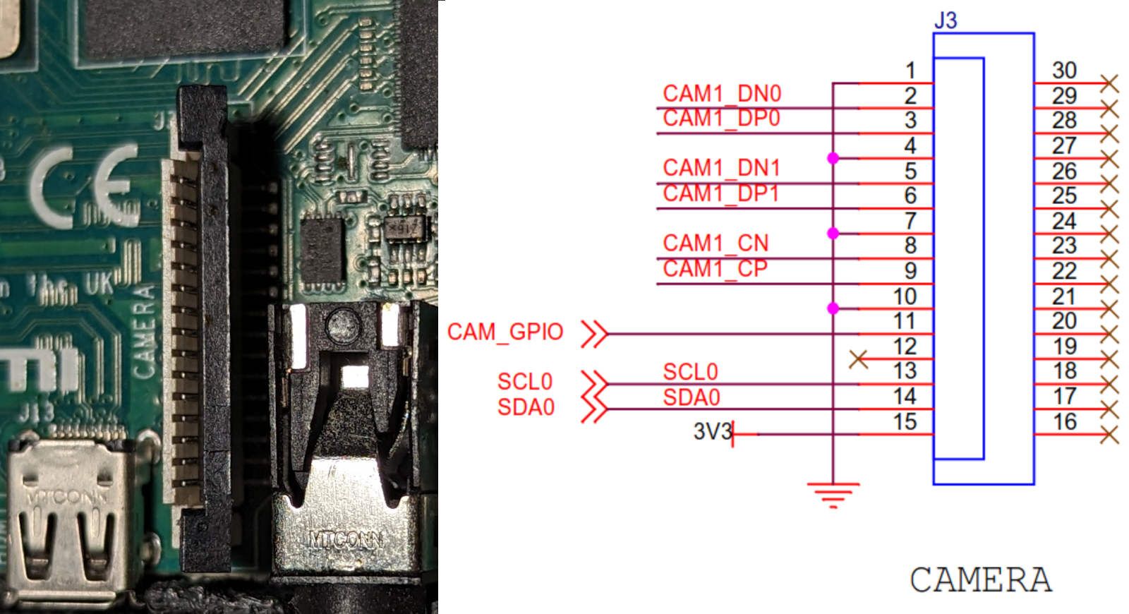
I've examined Raspberry PI 4 Model B schematics. According to schematics, camera connector has the following pinout and there is only one way to connect FFC cable to the connector.

I also checked that the GND pin is on the top and the 3V3 pin is on the bottom.

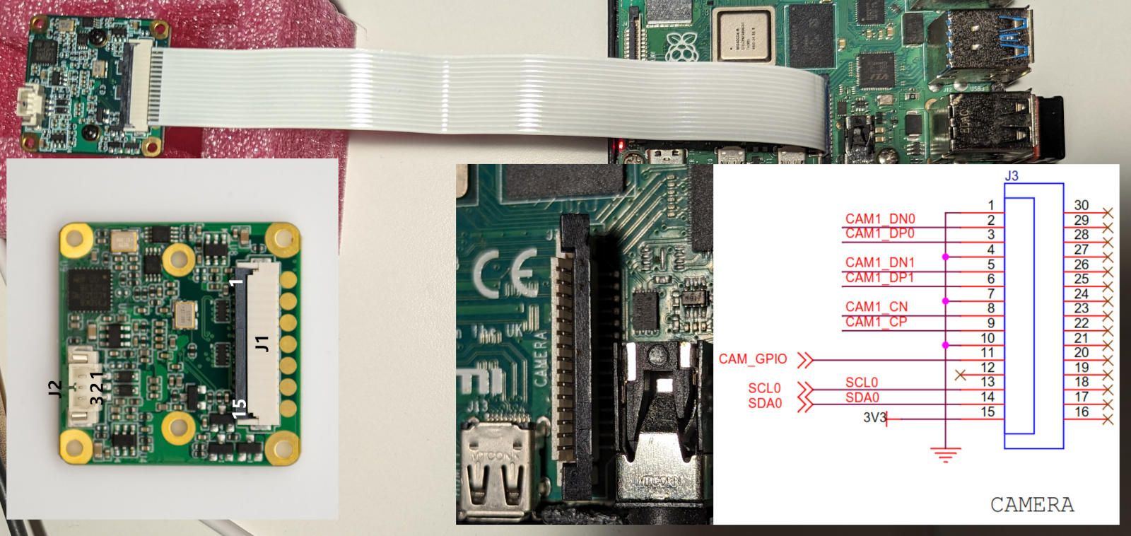
Entire connection diagram is as follows and this is the configuration I've used from the very beginning.

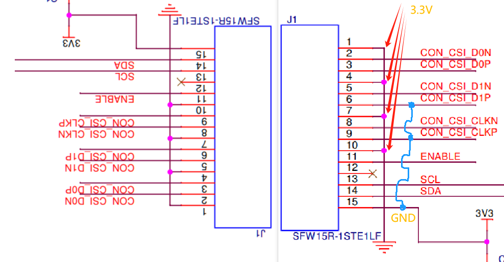
Since the camera connector allows FFC cable to be connected on both sides, I've connected cable with the opposite side.

In such connection scheme, the Raspberry Pi failed boot. It looks like there is a short circuit somewhere. But, Jetson Nano can handle that load ))) According to the readings from my power supply, power consumption increased from 2W to 10W and camera module gets extremely hot. It doesn't look like camera can work with such connection scheme.
Even after these experiments, I was able to connect to the camera and it did not report any errors.
user@raspberrypi:~/mv_tools_rpi $ ./mv_mipi_i2c.sh -b 10 -r -f manufacturer
Manufacturer is VEYE
user@raspberrypi:~/mv_tools_rpi $ ./mv_mipi_i2c.sh -b 10 -r -f model
model is RAW-MIPI-SC132M
user@raspberrypi:~/mv_tools_rpi $ ./mv_mipi_i2c.sh -b 10 -r -f errcode
errcode is 0x0
user@raspberrypi:~/mv_tools_rpi $ ./mv_mipi_i2c.sh -b 10 -r -f snsreg -p1 0x301f
read sensor register addr 0x301f value 0xf
Apparently both my modules are damaged and this cannot be detected with software.
-
@antony
You've made a very accurate analysis and testing, which is admirable.
For this camera model, to save space, we use a double-sided contact connector, which indeed has caused some issues. We are planning to improve this module by replacing it with a 22-pin single-sided contact connector.I, together with our hardware colleagues, conducted an analysis, and the results align with your test findings.
After reconnecting the FFC cable correctly following a reversal, the sensor's registers and error codes did not indicate a damaged state for the camera.
In the case of reversed power connection, the pins that are actually damaged are CON_CS_D1P and CON_CSI_CLKP. Unfortunately, this issue cannot be detected through software.