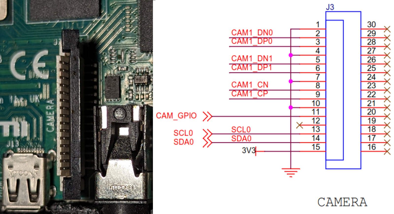
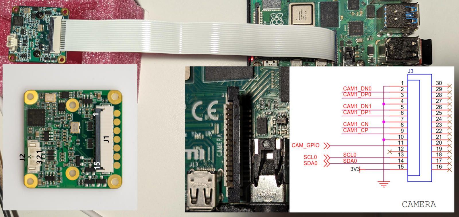
I've examined Raspberry PI 4 Model B schematics. According to schematics, camera connector has the following pinout and there is only one way to connect FFC cable to the connector.

I also checked that the GND pin is on the top and the 3V3 pin is on the bottom.

Entire connection diagram is as follows and this is the configuration I've used from the very beginning.

Since the camera connector allows FFC cable to be connected on both sides, I've connected cable with the opposite side.

In such connection scheme, the Raspberry Pi failed boot. It looks like there is a short circuit somewhere. But, Jetson Nano can handle that load ))) According to the readings from my power supply, power consumption increased from 2W to 10W and camera module gets extremely hot. It doesn't look like camera can work with such connection scheme.
Even after these experiments, I was able to connect to the camera and it did not report any errors.
user@raspberrypi:~/mv_tools_rpi $ ./mv_mipi_i2c.sh -b 10 -r -f manufacturer
Manufacturer is VEYE
user@raspberrypi:~/mv_tools_rpi $ ./mv_mipi_i2c.sh -b 10 -r -f model
model is RAW-MIPI-SC132M
user@raspberrypi:~/mv_tools_rpi $ ./mv_mipi_i2c.sh -b 10 -r -f errcode
errcode is 0x0
user@raspberrypi:~/mv_tools_rpi $ ./mv_mipi_i2c.sh -b 10 -r -f snsreg -p1 0x301f
read sensor register addr 0x301f value 0xf
Apparently both my modules are damaged and this cannot be detected with software.
