有关veye_mvcam驱动编译的问题
-
@潘阳刚
我们没有对接过edge2板子,看起来是khadas的kernel版本不支持报错的这几个ioctl命令。
你可以参考一下khadas平台原来支持的sensor的驱动,修改一下veye_mvcam.c的代码。
——比如注掉这几个ioctl,或者以其他方式实现这个功能。 -
@veye_xumm 您好,我注释掉了有关RKMODULE_GET_CSI_DSI_INFO的case,编译通过了,我连接好相机后却没能识别到相机。我使用的是i2c-3和i2c-4。
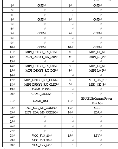
[   10.906532] mvcam 3-003b: veye mv series camera driver version: 01.01.04
[   11.909428] mvcam: mvcam_read: Reading register 0x04 failed
[   11.909481] mvcam 3-003b: failed to read chip id
[   11.909905] mvcam 4-003b: veye mv series camera driver version: 01.01.04
[   12.912928] mvcam: mvcam_read: Reading register 0x04 failed
[   12.913033] mvcam 4-003b: failed to read chip id
我觉得我的硬件连线没有问题,与电路原理图一一对应,通过定制的软线排连接。图像传感器也没有发热。我希望先排查软件方面的问题,但是我不知道该从何处开始排查起,或者有哪些可以使用的工具。图片里左侧为开发板相机接口线序,右侧为SC132M接口线序。
设备树相关代码:&csi2_dcphy0 { status = "okay"; ports { #address-cells = <1>; #size-cells = <0>; port@0 { reg = <0>; #address-cells = <1>; #size-cells = <0>; mipi_in_dcphy0: endpoint@1 { reg = <1>; remote-endpoint = <&mvcamb_out0>; data-lanes = <1 2>; }; }; port@1 { reg = <1>; #address-cells = <1>; #size-cells = <0>; csidcphy0_out: endpoint@0 { reg = <0>; remote-endpoint = <&mipi0_csi2_input>; }; }; }; }; &mipi_dcphy0 { status = "okay"; }; &csi2_dcphy1 { status = "okay"; ports { #address-cells = <1>; #size-cells = <0>; port@0 { reg = <0>; #address-cells = <1>; #size-cells = <0>; mipi_in_dcphy1: endpoint@1 { reg = <1>; remote-endpoint = <&mvcamf_out1>; data-lanes = <1 2>; }; }; port@1 { reg = <1>; #address-cells = <1>; #size-cells = <0>; csidcphy1_out: endpoint@0 { reg = <0>; remote-endpoint = <&mipi1_csi2_input>; }; }; }; }; &mipi_dcphy1 { status = "okay"; }; &csi2_dphy0 { status = "okay"; ports { #address-cells = <1>; #size-cells = <0>; port@0 { reg = <0>; #address-cells = <1>; #size-cells = <0>; mipidphy0_in_ucam0: endpoint@1 { reg = <1>; remote-endpoint = <&imx415c_out0>; data-lanes = <1 2 3 4>; }; }; port@1 { reg = <1>; #address-cells = <1>; #size-cells = <0>; csidphy0_out: endpoint@0 { reg = <0>; remote-endpoint = <&mipi2_csi2_input>; }; }; }; }; &csi2_dphy0_hw { status = "okay"; }; &i2c4 { status = "okay"; pinctrl-names = "default"; pinctrl-0 = <&i2c4m3_xfer>; dw9714b: dw9714b@c { compatible = "dongwoon,dw9714"; status = "okay"; reg = <0x0c>; pinctrl-names = "focusb_gpios"; pinctrl-0 = <&focusb_gpio>; focus-gpios = <&gpio1 RK_PA0 GPIO_ACTIVE_HIGH>; rockchip,vcm-start-current = <20>; rockchip,vcm-rated-current = <76>; rockchip,vcm-step-mode = <0>; rockchip,camera-module-index = <0>; rockchip,camera-module-facing = "back"; }; imx415b: imx415b@1a { compatible = "sony,imx415"; status = "okay"; reg = <0x1a>; clocks = <&cru CLK_MIPI_CAMARAOUT_M1>; clock-names = "xvclk"; power-domains = <&power RK3588_PD_VI>; pinctrl-names = "default", "camb_gpios"; pinctrl-0 = <&mipim1_camera1_clk>, <&camb_gpio>; rockchip,grf = <&sys_grf>; reset-gpios = <&gpio1 RK_PB2 GPIO_ACTIVE_LOW>; pwdn-gpios = <&gpio1 RK_PB3 GPIO_ACTIVE_HIGH>; rockchip,camera-module-index = <0>; rockchip,camera-module-facing = "back"; rockchip,camera-module-name = "CMK-OT2022-PX1"; rockchip,camera-module-lens-name = "IR0147-50IRC-8M-F20"; lens-focus = <&dw9714b>; port { imx415b_out0: endpoint { remote-endpoint = <&mipi_in_dcphy0>; data-lanes = <1 2 3 4>; }; }; }; mvcamb: mvcamb@3b{ compatible = "veye,mvcam"; reg = <0x3b>; clocks = <&cru CLK_MIPI_CAMARAOUT_M1>; clock-names = "xvclk"; pinctrl-names = "default"; pinctrl-0 = <&mipim1_camera1_clk>; power-domains = <&power RK3588_PD_VI>; //power-gpios = <&gpio4 RK_PB5 GPIO_ACTIVE_LOW>; reset-gpios = <&gpio1 RK_PB2 GPIO_ACTIVE_HIGH>;//&gpio3 RK_PC4 GPIO_ACTIVE_HIGH pwdn-gpios = <&gpio1 RK_PB3 GPIO_ACTIVE_HIGH>;//&gpio3 RK_PC1 GPIO_ACTIVE_HIGH //avdd-supply = <&vcc_mipidcphy0>; //firefly,clkout-enabled-index = <0>; rockchip,camera-module-index = <0>; rockchip,camera-module-facing = "back"; rockchip,camera-module-name = "NC"; rockchip,camera-module-lens-name = "NC"; port { mvcamb_out0: endpoint { remote-endpoint = <&mipi_in_dcphy0>;//&mipidphy0_in_ucam0 data-lanes = <1 2>; }; }; }; }; &i2c3 { status = "okay"; pinctrl-names = "default"; pinctrl-0 = <&i2c3m0_xfer>; dw9714f: dw9714f@c { compatible = "dongwoon,dw9714"; status = "okay"; reg = <0x0c>; pinctrl-names = "focusf_gpios"; pinctrl-0 = <&focusf_gpio>; focus-gpios = <&gpio1 RK_PA1 GPIO_ACTIVE_HIGH>; rockchip,vcm-start-current = <20>; rockchip,vcm-rated-current = <76>; rockchip,vcm-step-mode = <0>; rockchip,camera-module-index = <1>; rockchip,camera-module-facing = "front"; }; imx415f: imx415f@1a { compatible = "sony,imx415"; status = "okay"; reg = <0x1a>; clocks = <&cru CLK_MIPI_CAMARAOUT_M2>; clock-names = "xvclk"; power-domains = <&power RK3588_PD_VI>; pinctrl-names = "default", "camf_gpios"; pinctrl-0 = <&mipim1_camera2_clk>, <&camf_gpio>; rockchip,grf = <&sys_grf>; reset-gpios = <&gpio3 RK_PC6 GPIO_ACTIVE_LOW>; pwdn-gpios = <&gpio3 RK_PC5 GPIO_ACTIVE_HIGH>; rockchip,camera-module-index = <1>; rockchip,camera-module-facing = "front"; rockchip,camera-module-name = "CMK-OT2022-PX1"; rockchip,camera-module-lens-name = "IR0147-50IRC-8M-F20"; lens-focus = <&dw9714f>; port { imx415f_out1: endpoint { remote-endpoint = <&mipi_in_dcphy1>; data-lanes = <1 2 3 4>; }; }; }; mvcamf: mvcamf@3b{ compatible = "veye,mvcam"; reg = <0x3b>; clocks = <&cru CLK_MIPI_CAMARAOUT_M2>; clock-names = "xvclk"; pinctrl-names = "default"; pinctrl-0 = <&mipim1_camera2_clk>; power-domains = <&power RK3588_PD_VI>; //power-gpios = <&gpio4 RK_PB5 GPIO_ACTIVE_LOW>; reset-gpios = <&gpio3 RK_PC6 GPIO_ACTIVE_HIGH>;//&gpio3 RK_PC4 GPIO_ACTIVE_HIGH pwdn-gpios = <&gpio3 RK_PC5 GPIO_ACTIVE_HIGH>;//&gpio3 RK_PC1 GPIO_ACTIVE_HIGH //avdd-supply = <&vcc_mipidcphy0>; //firefly,clkout-enabled-index = <0>; rockchip,camera-module-index = <1>; rockchip,camera-module-facing = "back"; rockchip,camera-module-name = "NC"; rockchip,camera-module-lens-name = "NC"; port { mvcamf_out1: endpoint { remote-endpoint = <&mipi_in_dcphy1>;//&mipidphy0_in_ucam0 data-lanes = <1 2>; }; }; }; }; &i2c8 { status = "okay"; pinctrl-names = "default"; pinctrl-0 = <&i2c8m2_xfer>; dw9714c: dw9714c@c { compatible = "dongwoon,dw9714"; status = "okay"; reg = <0x0c>; pinctrl-names = "focusc_gpios"; pinctrl-0 = <&focusc_gpio>; focus-gpios = <&gpio1 RK_PA6 GPIO_ACTIVE_HIGH>; rockchip,vcm-start-current = <20>; rockchip,vcm-rated-current = <76>; rockchip,vcm-step-mode = <0>; rockchip,camera-module-index = <0>; rockchip,camera-module-facing = "back"; }; imx415: imx415@1a { compatible = "sony,imx415"; reg = <0x1a>; clocks = <&cru CLK_MIPI_CAMARAOUT_M3>; clock-names = "xvclk"; pinctrl-names = "default", "camc_gpios"; pinctrl-0 = <&mipim1_camera3_clk>, <&camc_gpio>; power-domains = <&power RK3588_PD_VI>; reset-gpios = <&gpio3 RK_PB4 GPIO_ACTIVE_LOW>; pwdn-gpios = <&gpio1 RK_PA4 GPIO_ACTIVE_HIGH>; rockchip,camera-module-index = <0>; rockchip,camera-module-facing = "back"; rockchip,camera-module-name = "CMK-OT2022-PX1"; rockchip,camera-module-lens-name = "IR0147-50IRC-8M-F20"; lens-focus = <&dw9714c>; port { imx415c_out0: endpoint { remote-endpoint = <&mipidphy0_in_ucam0>; data-lanes = <1 2 3 4>; }; }; }; }; &pinctrl { cam { camf_gpio: camf-gpio { rockchip,pins = <3 RK_PC6 RK_FUNC_GPIO &pcfg_pull_none>, <3 RK_PC5 RK_FUNC_GPIO &pcfg_pull_none>; }; camb_gpio: camb-gpio { rockchip,pins = <1 RK_PB2 RK_FUNC_GPIO &pcfg_pull_none>, <1 RK_PB3 RK_FUNC_GPIO &pcfg_pull_none>; }; camc_gpio: camc-gpio { rockchip,pins = <3 RK_PB4 RK_FUNC_GPIO &pcfg_pull_none>, <1 RK_PA4 RK_FUNC_GPIO &pcfg_pull_none>; }; focusb_gpio: focusb-gpio { rockchip,pins = <1 RK_PA0 RK_FUNC_GPIO &pcfg_pull_none>; }; focusf_gpio: focusf-gpio { rockchip,pins = <1 RK_PA1 RK_FUNC_GPIO &pcfg_pull_none>; }; focusc_gpio: focusc-gpio { rockchip,pins = <1 RK_PA6 RK_FUNC_GPIO &pcfg_pull_none>; }; }; }; &mipi0_csi2 { status = "okay"; ports { #address-cells = <1>; #size-cells = <0>; port@0 { reg = <0>; #address-cells = <1>; #size-cells = <0>; mipi0_csi2_input: endpoint@1 { reg = <1>; remote-endpoint = <&csidcphy0_out>; }; }; port@1 { reg = <1>; #address-cells = <1>; #size-cells = <0>; mipi0_csi2_output: endpoint@0 { reg = <0>; remote-endpoint = <&cif_mipi_in0>; }; }; }; }; &mipi1_csi2 { status = "okay"; ports { #address-cells = <1>; #size-cells = <0>; port@0 { reg = <0>; #address-cells = <1>; #size-cells = <0>; mipi1_csi2_input: endpoint@1 { reg = <1>; remote-endpoint = <&csidcphy1_out>; }; }; port@1 { reg = <1>; #address-cells = <1>; #size-cells = <0>; mipi1_csi2_output: endpoint@0 { reg = <0>; remote-endpoint = <&cif_mipi_in1>; }; }; }; }; &mipi2_csi2 { status = "okay"; ports { #address-cells = <1>; #size-cells = <0>; port@0 { reg = <0>; #address-cells = <1>; #size-cells = <0>; mipi2_csi2_input: endpoint@1 { reg = <1>; remote-endpoint = <&csidphy0_out>; }; }; port@1 { reg = <1>; #address-cells = <1>; #size-cells = <0>; mipi2_csi2_output: endpoint@0 { reg = <0>; remote-endpoint = <&cif_mipi2_in0>; }; }; }; }; &rkcif { status = "okay"; }; &rkcif_mipi_lvds { status = "okay"; port { cif_mipi_in0: endpoint { remote-endpoint = <&mipi0_csi2_output>; }; }; }; &rkcif_mipi_lvds_sditf { status = "okay"; port { mipi_lvds_sditf: endpoint { remote-endpoint = <&isp0_vir0>; }; }; }; &rkcif_mipi_lvds1 { status = "okay"; port { cif_mipi_in1: endpoint { remote-endpoint = <&mipi1_csi2_output>; }; }; }; &rkcif_mipi_lvds1_sditf { status = "okay"; port { mipi1_lvds_sditf: endpoint { remote-endpoint = <&isp0_vir1>; }; }; }; &rkcif_mipi_lvds2 { status = "okay"; port { cif_mipi2_in0: endpoint { remote-endpoint = <&mipi2_csi2_output>; }; }; }; &rkcif_mipi_lvds2_sditf { status = "okay"; port { mipi_lvds2_sditf: endpoint { remote-endpoint = <&isp1_vir0>; }; }; }; &rkcif_mmu { status = "okay"; }; &rkisp0 { status = "okay"; }; &isp0_mmu { status = "okay"; }; &rkisp0_vir0 { status = "okay"; port { #address-cells = <1>; #size-cells = <0>; isp0_vir0: endpoint@0 { reg = <0>; remote-endpoint = <&mipi_lvds_sditf>; }; }; }; &rkisp0_vir1 { status = "okay"; port { #address-cells = <1>; #size-cells = <0>; isp0_vir1: endpoint@0 { reg = <0>; remote-endpoint = <&mipi1_lvds_sditf>; }; }; }; &rkisp1 { status = "okay"; }; &isp1_mmu { status = "okay"; }; &rkisp1_vir0 { status = "okay"; port { #address-cells = <1>; #size-cells = <0>; isp1_vir0: endpoint@0 { reg = <0>; remote-endpoint = <&mipi_lvds2_sditf>; }; }; }; -
@潘阳刚 现在显示i2c不通。
你要检查两个。- 测量一下供电是否正常。
- 我们的11脚,也就是power enable引脚,你要确认是否拉高了? 如果没有拉高,需要修改一下dts。
-
@veye_xumm 11号引脚power enable需要多少V?我将该引脚拉高,电压表测量结果为1.8V,log显示没有检测到相机。我也检测了电源引脚,为3.3V,没有问题。
-
-
@潘阳刚 对的。我们的板子现在是3.3V标准的。i2c和power enable都是这个标准的。
-
@veye_xumm 有没有1.8V的其他图像传感器?
-
@潘阳刚 我们家的板子都是按照3.3V设计的。
-
你好,我在SC130这个摄像头驱动移植时也遇到这个问题,一开始我注释掉了有关RKMODULE_GET_CSI_DSI_INFO的case,编译通过了,但是无法出图,相机寄存器读取正常;尝试从另外一个SDK里将rk_moudle.h的RKMODULE_GET_CSI_DSI_INFO拷贝过来,进行测试目前还是不行,请问你怎么解决的?
-
@m4416202 请问取图的时候有什么报错吗? dts是否已根据你的主板上的硬件做了调整?
Hello! It looks like you're interested in this conversation, but you don't have an account yet.
Getting fed up of having to scroll through the same posts each visit? When you register for an account, you'll always come back to exactly where you were before, and choose to be notified of new replies (either via email, or push notification). You'll also be able to save bookmarks and upvote posts to show your appreciation to other community members.
With your input, this post could be even better 💗
Register Login