SOLVED rk3588开发板接RAW-MIPI-SC132M无法获取图片
-
@jihua
请执行一下uname -r,把结果发上来。
另外请检查一下你移植到的板子的mipi接口的原理图,用的哪个mipi接口,几lane的。 dts需要跟原理图对应起来才行。 -
硬件接口如下:
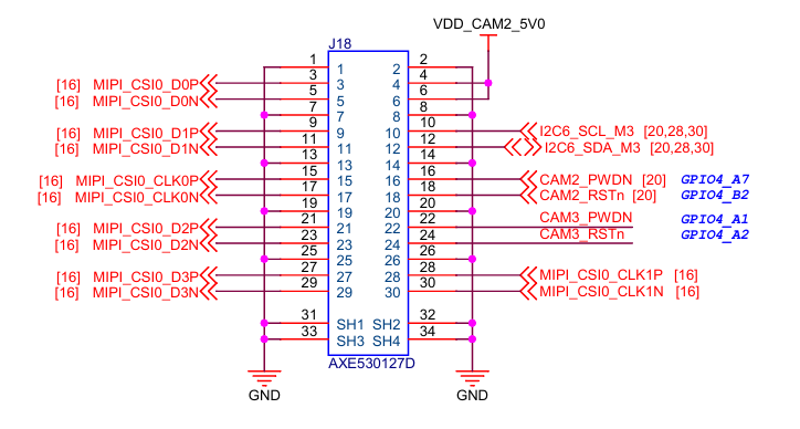
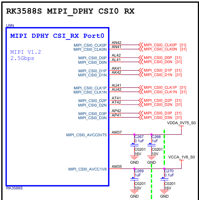

设备树配置如下:// SPDX-License-Identifier: (GPL-2.0+ OR MIT) /* * Copyright (c) 2020 Rockchip Electronics Co., Ltd. * */ / { vdd_cam2_5v: vdd-cam2-5v-regulator { compatible = "regulator-fixed"; regulator-name = "vdd_cam_5v"; regulator-always-on; regulator-boot-on; regulator-min-microvolt = <3300000>; regulator-max-microvolt = <3300000>; }; cam2_dovdd: cam2-dovdd { compatible = "regulator-fixed"; regulator-name = "cam_dovdd"; regulator-always-on; regulator-boot-on; regulator-min-microvolt = <1800000>; regulator-max-microvolt = <1800000>; vin-supply = <&vdd_cam2_5v>; }; cam2_avdd: cam2-avdd { compatible = "regulator-fixed"; regulator-name = "cam_avdd"; regulator-always-on; regulator-boot-on; regulator-min-microvolt = <2800000>; regulator-max-microvolt = <2800000>; vin-supply = <&vdd_cam2_5v>; }; cam2_dvdd: cam2-dvdd { compatible = "regulator-fixed"; regulator-name = "cam_dvdd"; regulator-always-on; regulator-boot-on; regulator-min-microvolt = <1200000>; regulator-max-microvolt = <1200000>; vin-supply = <&vdd_cam2_5v>; }; }; /* Link path: sensor->csi2_dphy0->mipi2_csi2->rkcif_mipi_lvds2--->rkcif_mipi_lvds2_sditf->rkisp0_vir2 */ &i2c6 { status = "okay"; pinctrl-names = "default"; pinctrl-0 = <&i2c6m3_xfer>; mvcam: mvcam@3b{ compatible = "veye,mvcam"; reg = <0x3b>; //clocks = <&cru CLK_MIPI_CAMARAOUT_M1>; //clock-names = "xvclk"; //pinctrl-names = "default"; //pinctrl-0 = <&mipim1_camera1_clk>; power-domains = <&power RK3588_PD_VI>; //power-gpios = <&gpio4 RK_PB5 GPIO_ACTIVE_LOW>; reset-gpios = <&gpio4 RK_PB2 GPIO_ACTIVE_HIGH>; pwdn-gpios = <&gpio4 RK_PA7 GPIO_ACTIVE_HIGH>; //avdd-supply = <&vcc_mipidcphy0>; //firefly,clkout-enabled-index = <0>; rockchip,camera-module-index = <0>; rockchip,camera-module-facing = "back"; rockchip,camera-module-name = "NC"; rockchip,camera-module-lens-name = "NC"; port { mvcam_out0: endpoint { remote-endpoint = <&mipidphy0_in_ucam0>; data-lanes = <1 2>; }; }; }; }; &csi2_dphy0_hw { status = "okay"; }; &csi2_dphy0 { status = "okay"; ports { #address-cells = <1>; #size-cells = <0>; port@0 { reg = <0>; #address-cells = <1>; #size-cells = <0>; mipidphy0_in_ucam0: endpoint@1 { reg = <1>; remote-endpoint = <&mvcam_out0>; data-lanes = <1 2>; }; }; port@1 { reg = <1>; #address-cells = <1>; #size-cells = <0>; csidphy0_out: endpoint@0 { reg = <0>; remote-endpoint = <&mipi2_csi2_input>; }; }; }; }; &mipi2_csi2 { status = "okay"; ports { #address-cells = <1>; #size-cells = <0>; port@0 { reg = <0>; #address-cells = <1>; #size-cells = <0>; mipi2_csi2_input: endpoint@1 { reg = <1>; remote-endpoint = <&csidphy0_out>; }; }; port@1 { reg = <1>; #address-cells = <1>; #size-cells = <0>; mipi2_csi2_output: endpoint@0 { reg = <0>; remote-endpoint = <&cif_mipi2_in0>; }; }; }; }; &rkcif { status = "okay"; }; &rkcif_mipi_lvds2 { status = "okay"; port { cif_mipi2_in0: endpoint { remote-endpoint = <&mipi2_csi2_output>; }; }; }; &rkcif_mipi_lvds2_sditf { status = "disabled"; port { mipi_lvds2_sditf: endpoint { remote-endpoint = <&isp1_vir0>; }; }; }; &rkcif_mmu { status = "okay"; }; &rkisp1 { status = "disabled"; }; &isp1_mmu { status = "disabled"; }; &rkisp1_vir0 { status = "disabled"; port { #address-cells = <1>; #size-cells = <0>; isp1_vir0: endpoint@0 { reg = <0>; remote-endpoint = <&mipi_lvds2_sditf>; }; }; }; -
@jihua 按照我们之前在飞凌板子上的经验,你第一个帖子上的错误提示无关的。
dts和原理图的对应关系的问题,你用的那个板子上有没有自带的支持的sensor?可作为参考。或者把之前系统自带的dts发个我对比看看。
一个终端取图,另一个终端运行一下dmesg,看看报什么错误吗? -
取图时的信息和dmesg信息如下:
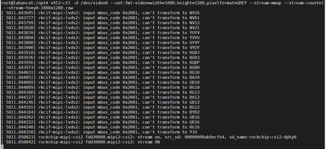
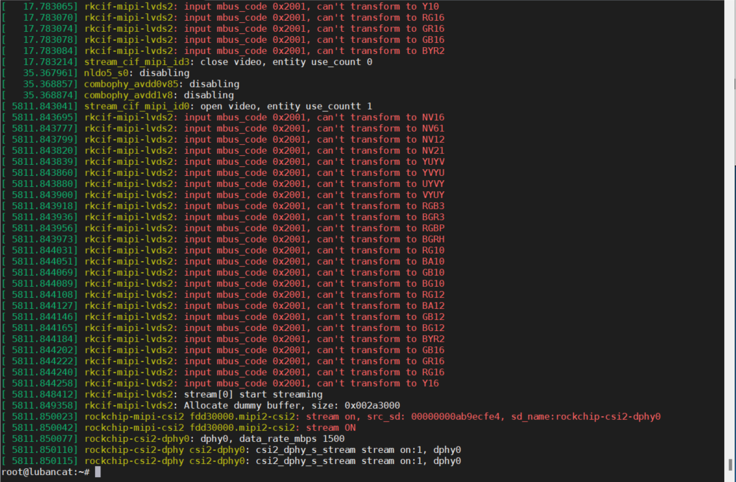
下面是原来系统里的设备树,接imx415是通的:// SPDX-License-Identifier: (GPL-2.0+ OR MIT) /* * Copyright (c) 2020 Rockchip Electronics Co., Ltd. * */ / { ext_cam2_37m_clk: external-camera-37m-clock { compatible = "fixed-clock"; clock-frequency = <37125000>; clock-output-names = "ext_cam_37m_clk"; #clock-cells = <0>; }; ext_cam2_25m_clk: external-camera-25m-clock { compatible = "fixed-clock"; clock-frequency = <25000000>; clock-output-names = "ext_cam_25m_clk"; #clock-cells = <0>; }; ext_cam2_24m_clk: external-camera-24m-clock { compatible = "fixed-clock"; #clock-cells = <0>; clock-frequency = <24000000>; clock-output-names = "ext_cam_24m_clk"; }; vdd_cam2_5v: vdd-cam2-5v-regulator { compatible = "regulator-fixed"; regulator-name = "vdd_cam_5v"; regulator-always-on; regulator-boot-on; regulator-min-microvolt = <3300000>; regulator-max-microvolt = <3300000>; }; cam2_dovdd: cam2-dovdd { compatible = "regulator-fixed"; regulator-name = "cam_dovdd"; regulator-always-on; regulator-boot-on; regulator-min-microvolt = <1800000>; regulator-max-microvolt = <1800000>; vin-supply = <&vdd_cam2_5v>; }; cam2_avdd: cam2-avdd { compatible = "regulator-fixed"; regulator-name = "cam_avdd"; regulator-always-on; regulator-boot-on; regulator-min-microvolt = <2800000>; regulator-max-microvolt = <2800000>; vin-supply = <&vdd_cam2_5v>; }; cam2_dvdd: cam2-dvdd { compatible = "regulator-fixed"; regulator-name = "cam_dvdd"; regulator-always-on; regulator-boot-on; regulator-min-microvolt = <1200000>; regulator-max-microvolt = <1200000>; vin-supply = <&vdd_cam2_5v>; }; }; /* Link path: sensor->csi2_dphy0->mipi2_csi2->rkcif_mipi_lvds2--->rkcif_mipi_lvds2_sditf->rkisp0_vir2 */ &i2c6 { status = "okay"; pinctrl-names = "default"; pinctrl-0 = <&i2c6m3_xfer>; dw9714: dw9714@c { status = "okay"; compatible = "dongwoon,dw9714"; reg = <0xc>; rockchip,camera-module-index = <0>; rockchip,vcm-max-current = <100>; rockchip,vcm-start-current = <0>; rockchip,vcm-rated-current = <100>; rockchip,vcm-step-mode = <0xd>; rockchip,vcm-dlc-enable = <0>; rockchip,vcm-mclk = <0>; rockchip,vcm-t-src = <0>; rockchip,camera-module-facing = "back"; }; ov5647: ov5647@36 { compatible = "ovti,ov5647"; status = "disabled"; reg = <0x36>; clocks = <&ext_cam2_25m_clk>; clock-names = "ext_cam_25m_clk"; pwdn-gpios = <&gpio4 RK_PA7 GPIO_ACTIVE_LOW>; lens-focus = <&dw9714>; port { ov5647_out: endpoint { remote-endpoint = <&dphy0_in_ov5647>; data-lanes = <1 2>; }; }; }; ov5648: camera@36 { compatible = "ovti,ov5648"; status = "disabled"; reg = <0x36>; clocks = <&ext_cam2_24m_clk>; clock-names = "xvclk"; dovdd-supply= <&cam2_dovdd>; /* 1.8v */ avdd-supply = <&cam2_avdd>; /* 2.8v */ dvdd-supply = <&cam2_dvdd>; /* 1.2v */ pwdn-gpios = <&gpio4 RK_PA7 GPIO_ACTIVE_HIGH>; reset-gpios = <&gpio4 RK_PB2 GPIO_ACTIVE_LOW>; rotation = <180>; rockchip,camera-module-index = <2>; rockchip,camera-module-facing = "back"; rockchip,camera-module-name = "THDS11073"; rockchip,camera-module-lens-name = "Largan-40122a1"; lens-focus = <&dw9714>; port { /* MIPI CSI-2 bus endpoint */ ov5648_out: endpoint { remote-endpoint = <&dphy0_in_ov5648>; clock-lanes = <0>; data-lanes = <1 2>; }; }; }; ov8858: ov8858@36 { compatible = "ovti,ov8858"; status = "disabled"; reg = <0x36>; clocks = <&ext_cam2_24m_clk>; clock-names = "xvclk"; dovdd-supply= <&cam2_dovdd>; /* 1.8v */ avdd-supply = <&cam2_avdd>; /* 2.8v */ dvdd-supply = <&cam2_dvdd>; /* 1.2v */ pwdn-gpios = <&gpio4 RK_PA7 GPIO_ACTIVE_HIGH>; reset-gpios = <&gpio4 RK_PB2 GPIO_ACTIVE_HIGH>; rotation = <180>; rockchip,camera-module-index = <2>; rockchip,camera-module-facing = "back"; rockchip,camera-module-name = "HS5885-BNSM1018-V01"; rockchip,camera-module-lens-name = "default"; lens-focus = <&dw9714>; port { /* MIPI CSI-2 bus endpoint */ ov8858_out: endpoint { remote-endpoint = <&dphy0_in_ov8858>; clock-lanes = <0>; data-lanes = <1 2>; }; }; }; ov13850: ov13850@10 { compatible = "ovti,ov13850"; status = "disabled"; reg = <0x10>; clocks = <&ext_cam2_24m_clk>; clock-names = "xvclk"; dovdd-supply= <&cam2_dovdd>; /* 1.8v */ avdd-supply = <&cam2_avdd>; /* 2.8v */ dvdd-supply = <&cam2_dvdd>; /* 1.2v */ pwdn-gpios = <&gpio4 RK_PA7 GPIO_ACTIVE_HIGH>; reset-gpios = <&gpio4 RK_PB2 GPIO_ACTIVE_HIGH>; rotation = <180>; rockchip,camera-module-index = <2>; rockchip,camera-module-facing = "back"; rockchip,camera-module-name = "ZC-OV13850R2A-V1"; rockchip,camera-module-lens-name = "Largan-50064B31"; lens-focus = <&dw9714>; port { /* MIPI CSI-2 bus endpoint */ ov13850_out: endpoint { remote-endpoint = <&dphy0_in_ov13850>; clock-lanes = <0>; data-lanes = <1 2>; }; }; }; imx415_2: imx415-2@1a { compatible = "sony,imx415"; status = "okay"; reg = <0x1a>; clocks = <&ext_cam2_37m_clk>; clock-names = "xvclk"; avdd-supply = <&cam2_avdd>; dovdd-supply = <&cam2_dovdd>; dvdd-supply = <&cam2_dvdd>; reset-gpios = <&gpio1 RK_PB2 GPIO_ACTIVE_LOW>; rockchip,camera-module-index = <2>; rockchip,camera-module-facing = "back"; rockchip,camera-module-name = "CMK-OT2022-PX1"; rockchip,camera-module-lens-name = "IR0147-50IRC-8M-F20"; port { imx415_out2: endpoint { remote-endpoint = <&dphy0_in_imx415>; data-lanes = <1 2 3 4>; }; }; }; }; &csi2_dphy0_hw { status = "okay"; }; &csi2_dphy0 { status = "okay"; ports { #address-cells = <1>; #size-cells = <0>; port@0 { reg = <0>; #address-cells = <1>; #size-cells = <0>; dphy0_in_ov5648: endpoint@1 { reg = <1>; remote-endpoint = <&ov5648_out>; data-lanes = <1 2>; }; dphy0_in_ov8858: endpoint@2 { reg = <2>; remote-endpoint = <&ov8858_out>; data-lanes = <1 2>; }; dphy0_in_ov13850: endpoint@3 { reg = <3>; remote-endpoint = <&ov13850_out>; data-lanes = <1 2>; }; dphy0_in_ov5647: endpoint@4 { reg = <4>; remote-endpoint = <&ov5647_out>; data-lanes = <1 2>; }; dphy0_in_imx415: endpoint@5 { reg = <5>; remote-endpoint = <&imx415_out2>; data-lanes = <1 2 3 4>; }; }; port@1 { reg = <1>; #address-cells = <1>; #size-cells = <0>; csidphy0_out: endpoint@0 { reg = <0>; remote-endpoint = <&mipi2_csi2_input>; }; }; }; }; &mipi2_csi2 { status = "okay"; ports { #address-cells = <1>; #size-cells = <0>; port@0 { reg = <0>; #address-cells = <1>; #size-cells = <0>; mipi2_csi2_input: endpoint@1 { reg = <1>; remote-endpoint = <&csidphy0_out>; }; }; port@1 { reg = <1>; #address-cells = <1>; #size-cells = <0>; mipi2_csi2_output: endpoint@0 { reg = <0>; remote-endpoint = <&cif_mipi2_in0>; }; }; }; }; &rkcif { status = "okay"; }; &rkcif_mipi_lvds2 { status = "okay"; port { cif_mipi2_in0: endpoint { remote-endpoint = <&mipi2_csi2_output>; }; }; }; &rkcif_mipi_lvds2_sditf { status = "okay"; port { mipi_lvds2_sditf: endpoint { remote-endpoint = <&isp1_vir0>; }; }; }; &rkcif_mmu { status = "okay"; }; &rkisp1 { status = "okay"; }; &isp1_mmu { status = "okay"; }; &rkisp1_vir0 { status = "okay"; port { #address-cells = <1>; #size-cells = <0>; isp1_vir0: endpoint@0 { reg = <0>; remote-endpoint = <&mipi_lvds2_sditf>; }; }; }; -
@jihua dts这么看,看不出啥问题。
你是不是有一个转接板,这个板子原理应该没问题的吧?
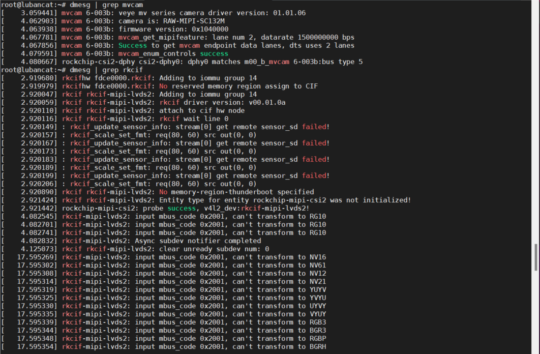
另外你现在接我们sc132,启动之后
dmesg | grep mvcam
dmesg | grep rkcif
发给我看一下 -
执行指令结果如下:
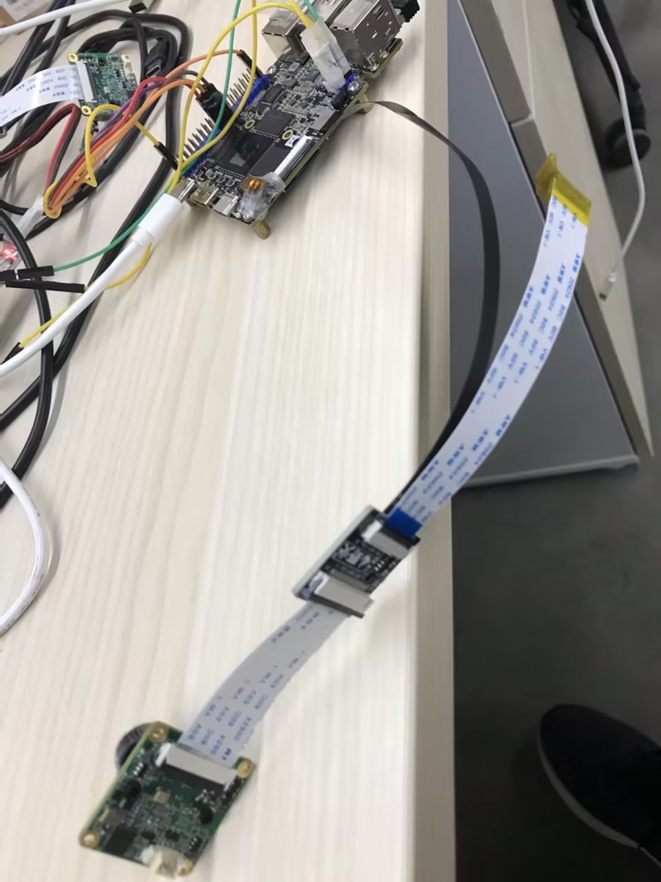
硬件是有转接板的,量过了线序是对应的上的:
 [图片]
[图片] -
@jihua
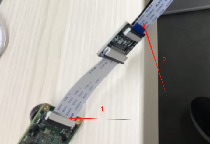
1处排线插歪了。
2处的排线没有用处建议去掉,保证mipi信号的质量。不过感觉你这个的核心问题还是

-
@veye_xumm
读取相机的datarate返回是-1代表什么意思。

-
@jihua 应该是这个版本的固件还没有支持这个寄存器。不影响正常出图和对接的。
-
@veye_xumm
内核打印的信息显示datarate是1.5G,用示波器测量不到时钟波形,只能测到数据波形,这个模块的实际datarate是多少的?现在抓图的时候,内核驱动报crc错误,怀疑是排线太长或者datarate对不上。

-
@jihua
按照1.5G配置是没问题的,我们在多个rk3588上面都调通的。
你用的排线是多长的?可否拍个照片我看看。 -
@veye_xumm
排线长度有26厘米长
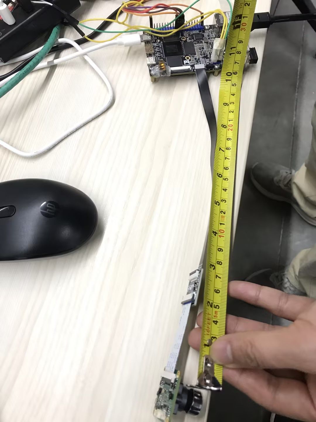 [图片]
[图片] -
@jihua 线长也没有很夸张。你测测摄像头这端,入口地方的3.3V供电,实际电压是多少?
-
@veye_xumm
VCC3V3 测量到是3.3V,MIPI_CK_N 时钟是固定的吗?时钟是多少的?设置帧率后这个时钟会变吗? -
@jihua 相机是固定的1188M,3588那头设置为1500M是没问题的。
你把现在报的错发给我看看。 -
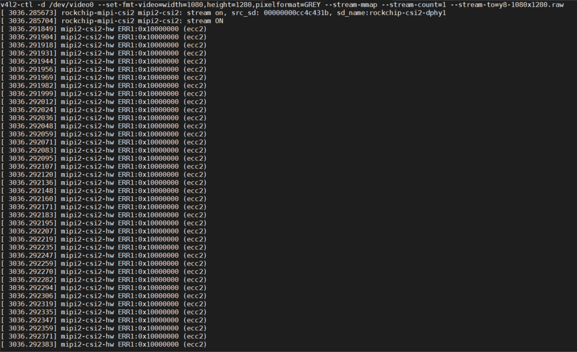
@veye_xumm
获取一张图片报错
-
@jihua 我们在rk平台没有遇到过这个问题。看ecc2这个错误提示的话,像是mipi信号劣化了。