rk3588开发板接RAW-MIPI-SC132M无法获取图片


-
模块上电后,查看触发模式是流模式,配置imgacq为1后,读取图片阻塞不动一直读取不到图片,用示波器测量lane clk pin无信号。
-
@jihua
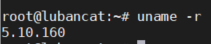
请执行一下uname -r,把结果发上来。
另外请检查一下你移植到的板子的mipi接口的原理图,用的哪个mipi接口,几lane的。 dts需要跟原理图对应起来才行。 -
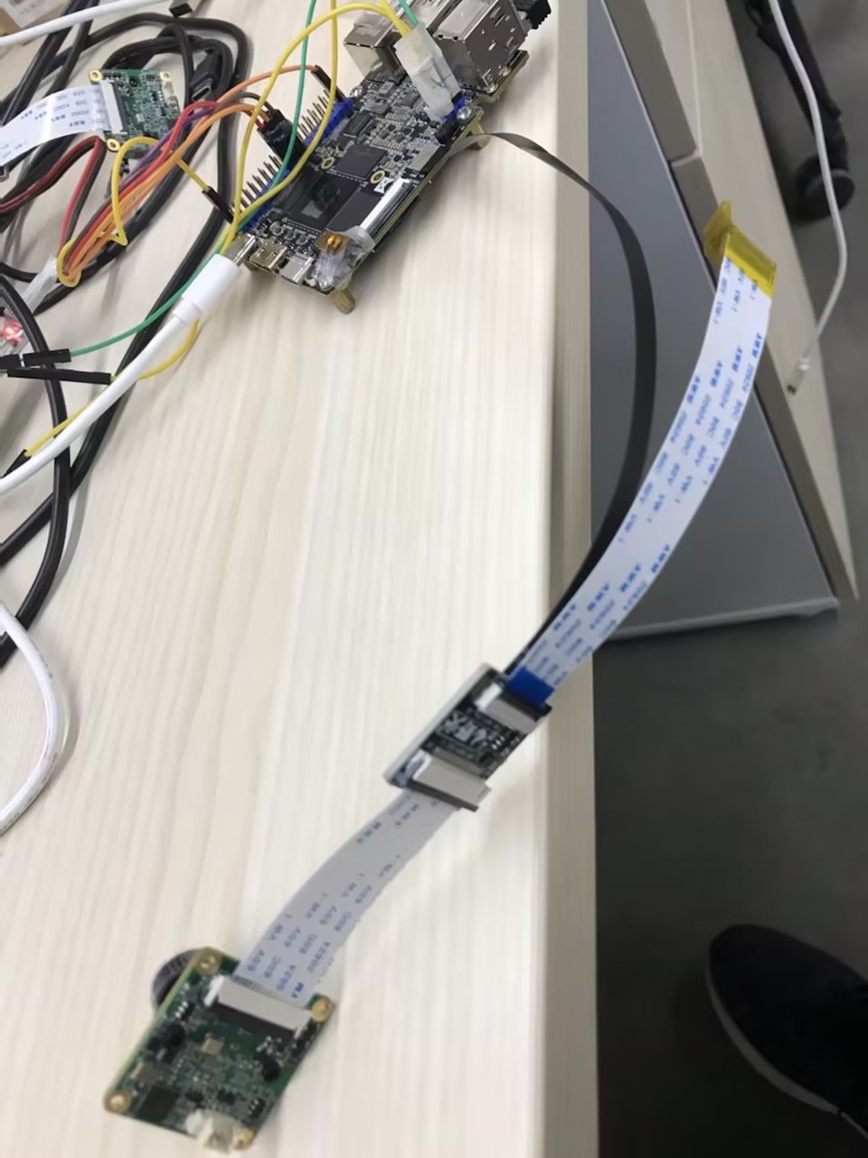
硬件接口如下:
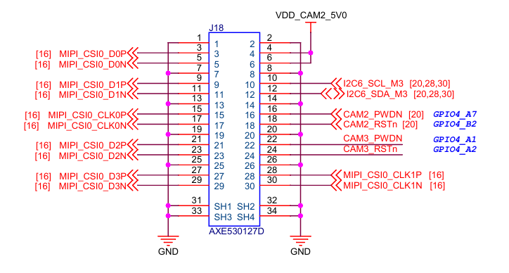
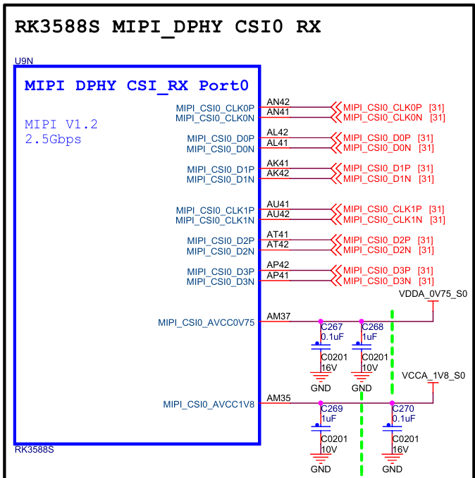
设备树配置如下:// SPDX-License-Identifier: (GPL-2.0+ OR MIT) /* * Copyright (c) 2020 Rockchip Electronics Co., Ltd. * */ / { vdd_cam2_5v: vdd-cam2-5v-regulator { compatible = "regulator-fixed"; regulator-name = "vdd_cam_5v"; regulator-always-on; regulator-boot-on; regulator-min-microvolt = <3300000>; regulator-max-microvolt = <3300000>; }; cam2_dovdd: cam2-dovdd { compatible = "regulator-fixed"; regulator-name = "cam_dovdd"; regulator-always-on; regulator-boot-on; regulator-min-microvolt = <1800000>; regulator-max-microvolt = <1800000>; vin-supply = <&vdd_cam2_5v>; }; cam2_avdd: cam2-avdd { compatible = "regulator-fixed"; regulator-name = "cam_avdd"; regulator-always-on; regulator-boot-on; regulator-min-microvolt = <2800000>; regulator-max-microvolt = <2800000>; vin-supply = <&vdd_cam2_5v>; }; cam2_dvdd: cam2-dvdd { compatible = "regulator-fixed"; regulator-name = "cam_dvdd"; regulator-always-on; regulator-boot-on; regulator-min-microvolt = <1200000>; regulator-max-microvolt = <1200000>; vin-supply = <&vdd_cam2_5v>; }; }; /* Link path: sensor->csi2_dphy0->mipi2_csi2->rkcif_mipi_lvds2--->rkcif_mipi_lvds2_sditf->rkisp0_vir2 */ &i2c6 { status = "okay"; pinctrl-names = "default"; pinctrl-0 = <&i2c6m3_xfer>; mvcam: mvcam@3b{ compatible = "veye,mvcam"; reg = <0x3b>; //clocks = <&cru CLK_MIPI_CAMARAOUT_M1>; //clock-names = "xvclk"; //pinctrl-names = "default"; //pinctrl-0 = <&mipim1_camera1_clk>; power-domains = <&power RK3588_PD_VI>; //power-gpios = <&gpio4 RK_PB5 GPIO_ACTIVE_LOW>; reset-gpios = <&gpio4 RK_PB2 GPIO_ACTIVE_HIGH>; pwdn-gpios = <&gpio4 RK_PA7 GPIO_ACTIVE_HIGH>; //avdd-supply = <&vcc_mipidcphy0>; //firefly,clkout-enabled-index = <0>; rockchip,camera-module-index = <0>; rockchip,camera-module-facing = "back"; rockchip,camera-module-name = "NC"; rockchip,camera-module-lens-name = "NC"; port { mvcam_out0: endpoint { remote-endpoint = <&mipidphy0_in_ucam0>; data-lanes = <1 2>; }; }; }; }; &csi2_dphy0_hw { status = "okay"; }; &csi2_dphy0 { status = "okay"; ports { #address-cells = <1>; #size-cells = <0>; port@0 { reg = <0>; #address-cells = <1>; #size-cells = <0>; mipidphy0_in_ucam0: endpoint@1 { reg = <1>; remote-endpoint = <&mvcam_out0>; data-lanes = <1 2>; }; }; port@1 { reg = <1>; #address-cells = <1>; #size-cells = <0>; csidphy0_out: endpoint@0 { reg = <0>; remote-endpoint = <&mipi2_csi2_input>; }; }; }; }; &mipi2_csi2 { status = "okay"; ports { #address-cells = <1>; #size-cells = <0>; port@0 { reg = <0>; #address-cells = <1>; #size-cells = <0>; mipi2_csi2_input: endpoint@1 { reg = <1>; remote-endpoint = <&csidphy0_out>; }; }; port@1 { reg = <1>; #address-cells = <1>; #size-cells = <0>; mipi2_csi2_output: endpoint@0 { reg = <0>; remote-endpoint = <&cif_mipi2_in0>; }; }; }; }; &rkcif { status = "okay"; }; &rkcif_mipi_lvds2 { status = "okay"; port { cif_mipi2_in0: endpoint { remote-endpoint = <&mipi2_csi2_output>; }; }; }; &rkcif_mipi_lvds2_sditf { status = "disabled"; port { mipi_lvds2_sditf: endpoint { remote-endpoint = <&isp1_vir0>; }; }; }; &rkcif_mmu { status = "okay"; }; &rkisp1 { status = "disabled"; }; &isp1_mmu { status = "disabled"; }; &rkisp1_vir0 { status = "disabled"; port { #address-cells = <1>; #size-cells = <0>; isp1_vir0: endpoint@0 { reg = <0>; remote-endpoint = <&mipi_lvds2_sditf>; }; }; }; -
@jihua 按照我们之前在飞凌板子上的经验,你第一个帖子上的错误提示无关的。
dts和原理图的对应关系的问题,你用的那个板子上有没有自带的支持的sensor?可作为参考。或者把之前系统自带的dts发个我对比看看。
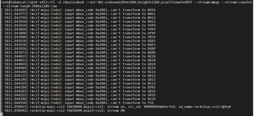
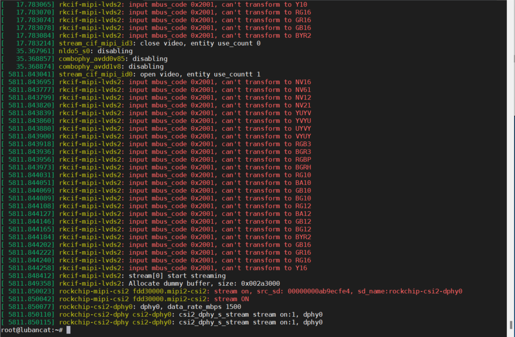
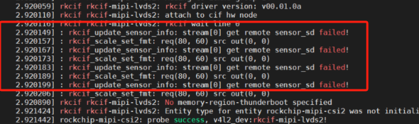
一个终端取图,另一个终端运行一下dmesg,看看报什么错误吗? -
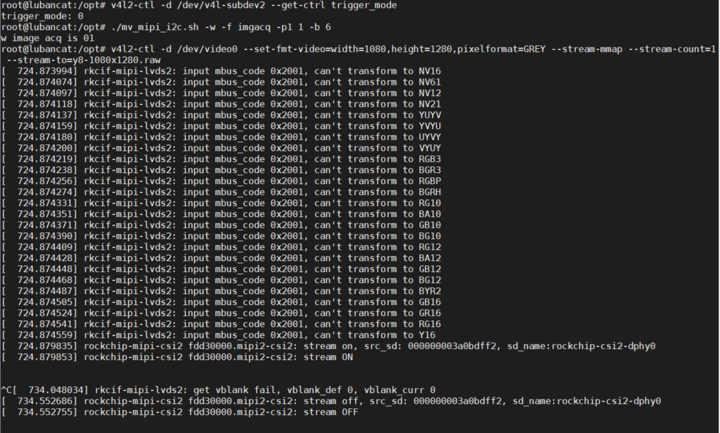
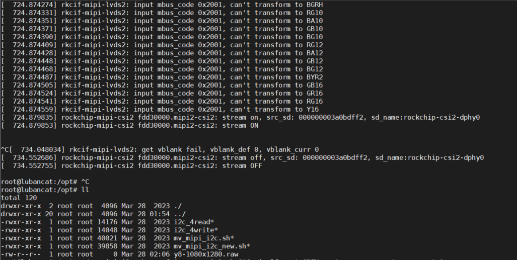
取图时的信息和dmesg信息如下:
下面是原来系统里的设备树,接imx415是通的:// SPDX-License-Identifier: (GPL-2.0+ OR MIT) /* * Copyright (c) 2020 Rockchip Electronics Co., Ltd. * */ / { ext_cam2_37m_clk: external-camera-37m-clock { compatible = "fixed-clock"; clock-frequency = <37125000>; clock-output-names = "ext_cam_37m_clk"; #clock-cells = <0>; }; ext_cam2_25m_clk: external-camera-25m-clock { compatible = "fixed-clock"; clock-frequency = <25000000>; clock-output-names = "ext_cam_25m_clk"; #clock-cells = <0>; }; ext_cam2_24m_clk: external-camera-24m-clock { compatible = "fixed-clock"; #clock-cells = <0>; clock-frequency = <24000000>; clock-output-names = "ext_cam_24m_clk"; }; vdd_cam2_5v: vdd-cam2-5v-regulator { compatible = "regulator-fixed"; regulator-name = "vdd_cam_5v"; regulator-always-on; regulator-boot-on; regulator-min-microvolt = <3300000>; regulator-max-microvolt = <3300000>; }; cam2_dovdd: cam2-dovdd { compatible = "regulator-fixed"; regulator-name = "cam_dovdd"; regulator-always-on; regulator-boot-on; regulator-min-microvolt = <1800000>; regulator-max-microvolt = <1800000>; vin-supply = <&vdd_cam2_5v>; }; cam2_avdd: cam2-avdd { compatible = "regulator-fixed"; regulator-name = "cam_avdd"; regulator-always-on; regulator-boot-on; regulator-min-microvolt = <2800000>; regulator-max-microvolt = <2800000>; vin-supply = <&vdd_cam2_5v>; }; cam2_dvdd: cam2-dvdd { compatible = "regulator-fixed"; regulator-name = "cam_dvdd"; regulator-always-on; regulator-boot-on; regulator-min-microvolt = <1200000>; regulator-max-microvolt = <1200000>; vin-supply = <&vdd_cam2_5v>; }; }; /* Link path: sensor->csi2_dphy0->mipi2_csi2->rkcif_mipi_lvds2--->rkcif_mipi_lvds2_sditf->rkisp0_vir2 */ &i2c6 { status = "okay"; pinctrl-names = "default"; pinctrl-0 = <&i2c6m3_xfer>; dw9714: dw9714@c { status = "okay"; compatible = "dongwoon,dw9714"; reg = <0xc>; rockchip,camera-module-index = <0>; rockchip,vcm-max-current = <100>; rockchip,vcm-start-current = <0>; rockchip,vcm-rated-current = <100>; rockchip,vcm-step-mode = <0xd>; rockchip,vcm-dlc-enable = <0>; rockchip,vcm-mclk = <0>; rockchip,vcm-t-src = <0>; rockchip,camera-module-facing = "back"; }; ov5647: ov5647@36 { compatible = "ovti,ov5647"; status = "disabled"; reg = <0x36>; clocks = <&ext_cam2_25m_clk>; clock-names = "ext_cam_25m_clk"; pwdn-gpios = <&gpio4 RK_PA7 GPIO_ACTIVE_LOW>; lens-focus = <&dw9714>; port { ov5647_out: endpoint { remote-endpoint = <&dphy0_in_ov5647>; data-lanes = <1 2>; }; }; }; ov5648: camera@36 { compatible = "ovti,ov5648"; status = "disabled"; reg = <0x36>; clocks = <&ext_cam2_24m_clk>; clock-names = "xvclk"; dovdd-supply= <&cam2_dovdd>; /* 1.8v */ avdd-supply = <&cam2_avdd>; /* 2.8v */ dvdd-supply = <&cam2_dvdd>; /* 1.2v */ pwdn-gpios = <&gpio4 RK_PA7 GPIO_ACTIVE_HIGH>; reset-gpios = <&gpio4 RK_PB2 GPIO_ACTIVE_LOW>; rotation = <180>; rockchip,camera-module-index = <2>; rockchip,camera-module-facing = "back"; rockchip,camera-module-name = "THDS11073"; rockchip,camera-module-lens-name = "Largan-40122a1"; lens-focus = <&dw9714>; port { /* MIPI CSI-2 bus endpoint */ ov5648_out: endpoint { remote-endpoint = <&dphy0_in_ov5648>; clock-lanes = <0>; data-lanes = <1 2>; }; }; }; ov8858: ov8858@36 { compatible = "ovti,ov8858"; status = "disabled"; reg = <0x36>; clocks = <&ext_cam2_24m_clk>; clock-names = "xvclk"; dovdd-supply= <&cam2_dovdd>; /* 1.8v */ avdd-supply = <&cam2_avdd>; /* 2.8v */ dvdd-supply = <&cam2_dvdd>; /* 1.2v */ pwdn-gpios = <&gpio4 RK_PA7 GPIO_ACTIVE_HIGH>; reset-gpios = <&gpio4 RK_PB2 GPIO_ACTIVE_HIGH>; rotation = <180>; rockchip,camera-module-index = <2>; rockchip,camera-module-facing = "back"; rockchip,camera-module-name = "HS5885-BNSM1018-V01"; rockchip,camera-module-lens-name = "default"; lens-focus = <&dw9714>; port { /* MIPI CSI-2 bus endpoint */ ov8858_out: endpoint { remote-endpoint = <&dphy0_in_ov8858>; clock-lanes = <0>; data-lanes = <1 2>; }; }; }; ov13850: ov13850@10 { compatible = "ovti,ov13850"; status = "disabled"; reg = <0x10>; clocks = <&ext_cam2_24m_clk>; clock-names = "xvclk"; dovdd-supply= <&cam2_dovdd>; /* 1.8v */ avdd-supply = <&cam2_avdd>; /* 2.8v */ dvdd-supply = <&cam2_dvdd>; /* 1.2v */ pwdn-gpios = <&gpio4 RK_PA7 GPIO_ACTIVE_HIGH>; reset-gpios = <&gpio4 RK_PB2 GPIO_ACTIVE_HIGH>; rotation = <180>; rockchip,camera-module-index = <2>; rockchip,camera-module-facing = "back"; rockchip,camera-module-name = "ZC-OV13850R2A-V1"; rockchip,camera-module-lens-name = "Largan-50064B31"; lens-focus = <&dw9714>; port { /* MIPI CSI-2 bus endpoint */ ov13850_out: endpoint { remote-endpoint = <&dphy0_in_ov13850>; clock-lanes = <0>; data-lanes = <1 2>; }; }; }; imx415_2: imx415-2@1a { compatible = "sony,imx415"; status = "okay"; reg = <0x1a>; clocks = <&ext_cam2_37m_clk>; clock-names = "xvclk"; avdd-supply = <&cam2_avdd>; dovdd-supply = <&cam2_dovdd>; dvdd-supply = <&cam2_dvdd>; reset-gpios = <&gpio1 RK_PB2 GPIO_ACTIVE_LOW>; rockchip,camera-module-index = <2>; rockchip,camera-module-facing = "back"; rockchip,camera-module-name = "CMK-OT2022-PX1"; rockchip,camera-module-lens-name = "IR0147-50IRC-8M-F20"; port { imx415_out2: endpoint { remote-endpoint = <&dphy0_in_imx415>; data-lanes = <1 2 3 4>; }; }; }; }; &csi2_dphy0_hw { status = "okay"; }; &csi2_dphy0 { status = "okay"; ports { #address-cells = <1>; #size-cells = <0>; port@0 { reg = <0>; #address-cells = <1>; #size-cells = <0>; dphy0_in_ov5648: endpoint@1 { reg = <1>; remote-endpoint = <&ov5648_out>; data-lanes = <1 2>; }; dphy0_in_ov8858: endpoint@2 { reg = <2>; remote-endpoint = <&ov8858_out>; data-lanes = <1 2>; }; dphy0_in_ov13850: endpoint@3 { reg = <3>; remote-endpoint = <&ov13850_out>; data-lanes = <1 2>; }; dphy0_in_ov5647: endpoint@4 { reg = <4>; remote-endpoint = <&ov5647_out>; data-lanes = <1 2>; }; dphy0_in_imx415: endpoint@5 { reg = <5>; remote-endpoint = <&imx415_out2>; data-lanes = <1 2 3 4>; }; }; port@1 { reg = <1>; #address-cells = <1>; #size-cells = <0>; csidphy0_out: endpoint@0 { reg = <0>; remote-endpoint = <&mipi2_csi2_input>; }; }; }; }; &mipi2_csi2 { status = "okay"; ports { #address-cells = <1>; #size-cells = <0>; port@0 { reg = <0>; #address-cells = <1>; #size-cells = <0>; mipi2_csi2_input: endpoint@1 { reg = <1>; remote-endpoint = <&csidphy0_out>; }; }; port@1 { reg = <1>; #address-cells = <1>; #size-cells = <0>; mipi2_csi2_output: endpoint@0 { reg = <0>; remote-endpoint = <&cif_mipi2_in0>; }; }; }; }; &rkcif { status = "okay"; }; &rkcif_mipi_lvds2 { status = "okay"; port { cif_mipi2_in0: endpoint { remote-endpoint = <&mipi2_csi2_output>; }; }; }; &rkcif_mipi_lvds2_sditf { status = "okay"; port { mipi_lvds2_sditf: endpoint { remote-endpoint = <&isp1_vir0>; }; }; }; &rkcif_mmu { status = "okay"; }; &rkisp1 { status = "okay"; }; &isp1_mmu { status = "okay"; }; &rkisp1_vir0 { status = "okay"; port { #address-cells = <1>; #size-cells = <0>; isp1_vir0: endpoint@0 { reg = <0>; remote-endpoint = <&mipi_lvds2_sditf>; }; }; }; -
@jihua dts这么看,看不出啥问题。
你是不是有一个转接板,这个板子原理应该没问题的吧?
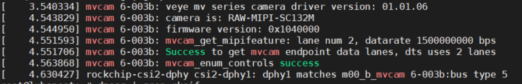
另外你现在接我们sc132,启动之后
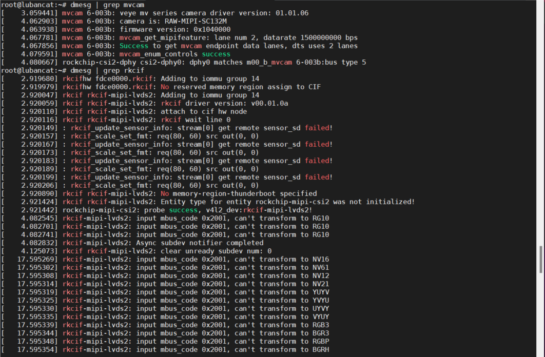
dmesg | grep mvcam
dmesg | grep rkcif
发给我看一下 -
执行指令结果如下:
硬件是有转接板的,量过了线序是对应的上的:
 [图片]
[图片] -
@jihua
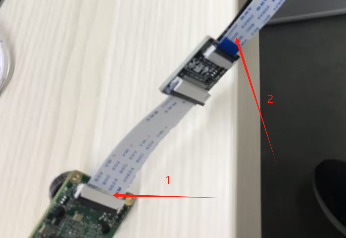
1处排线插歪了。
2处的排线没有用处建议去掉,保证mipi信号的质量。不过感觉你这个的核心问题还是
-
@veye_xumm
读取相机的datarate返回是-1代表什么意思。
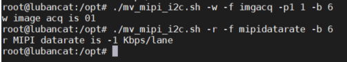
-
@jihua 应该是这个版本的固件还没有支持这个寄存器。不影响正常出图和对接的。
-
@veye_xumm
内核打印的信息显示datarate是1.5G,用示波器测量不到时钟波形,只能测到数据波形,这个模块的实际datarate是多少的?现在抓图的时候,内核驱动报crc错误,怀疑是排线太长或者datarate对不上。
-
@jihua
按照1.5G配置是没问题的,我们在多个rk3588上面都调通的。
你用的排线是多长的?可否拍个照片我看看。 -
@veye_xumm
排线长度有26厘米长
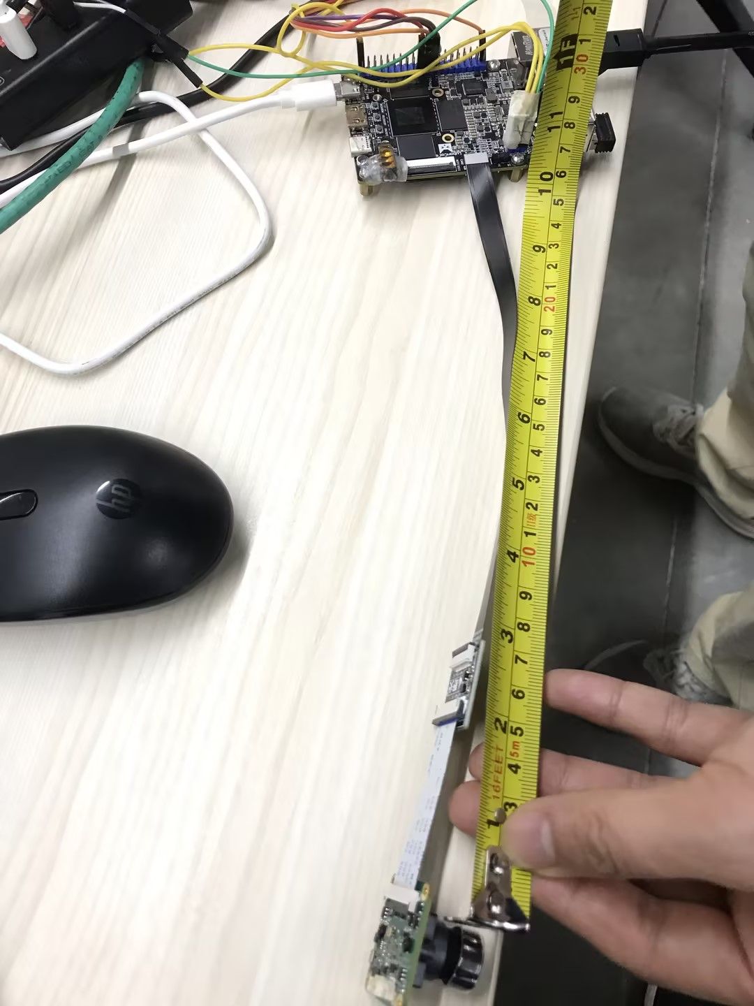 [图片]
[图片] -
@jihua 线长也没有很夸张。你测测摄像头这端,入口地方的3.3V供电,实际电压是多少?
-
@veye_xumm
VCC3V3 测量到是3.3V,MIPI_CK_N 时钟是固定的吗?时钟是多少的?设置帧率后这个时钟会变吗? -
@jihua 相机是固定的1188M,3588那头设置为1500M是没问题的。
你把现在报的错发给我看看。 -
@veye_xumm
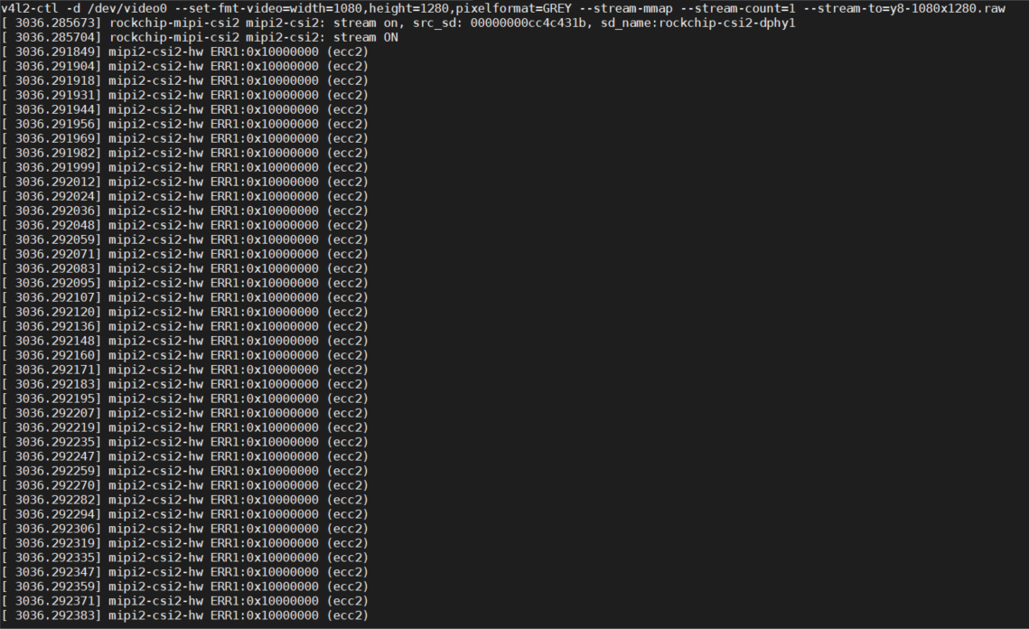
获取一张图片报错
-
@jihua 我们在rk平台没有遇到过这个问题。看ecc2这个错误提示的话,像是mipi信号劣化了。
Hello! It looks like you're interested in this conversation, but you don't have an account yet.
Getting fed up of having to scroll through the same posts each visit? When you register for an account, you'll always come back to exactly where you were before, and choose to be notified of new replies (either via email, or push notification). You'll also be able to save bookmarks and upvote posts to show your appreciation to other community members.
With your input, this post could be even better 💗
Register Login