Camera sync mode
-
@veye_xumm
Thanks for your answer.Did I understand that correctly. The connections should look like this:
One wire from - to
J6 pin 2 - J8 pin 2
J6 pin 2 - J8 pin 2
J6 pin 4 - J8 pin 4
J6 pin 6 - J8 pin 6 -
@g-towboat said in Camera sync mode:
@veye_xumm
Thanks for your answer.Did I understand that correctly. The connections should look like this:
One wire from - to
J6 pin 2 - J8 pin 2
J6 pin 4 - J8 pin 4
J6 pin 6 - J8 pin 6I think you just need to connect 2 4 6 8 pins of J6 and J8 together.
And all 1 2 3 4 5 6 7 8 pins of J6 and J8 together will work too. -
@veye_xumm
i'm sorry, but i still haven't got it. Can you describe it in a table e.g.:
J6 Pin X - J8 Pin YThank you
-
It's not some pairs of connection. It's a group of connection.
For example:
J6-2 is the source of XVS, and J6-4 J6-6 J6-8 J8-2 J8-4 J8-6 J8-8 are all sink of XVS.
So what you need to do is connect all these pins together.J6-1 J6-3 J6-5 J6-7 are already connected together on the board.
J8-1 J8-3 J8-5 J8-7 are already connected together on the board.
You can use them if you want.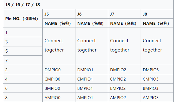
-
This post is deleted! -
e.g my post here:
http://forum.veye.cc/topic/21/camera-i2c-configuaration-for-sync-modeI just have blue images like the post here:
http://forum.veye.cc/topic/22/i-want-to-synchronize-the-two-cameras-in-sync-mode
But i have 8 cameras connected.Do I also connect the boards: FPD-LINK3-2RX?
or is it the i2c configuration? -
@g-towboat
Since you use CS-FPD-XAVIER-nCAM-IMX307, FPD-LINK3-2RX is a part of this module. -
@g-towboat
You can post your hardware connection here, I'll check it for you. -
I think it's worked now, i have made an Firmware update of each camera. What is the best way to check synchronization?
-
-
@veye_xumm I still have blue Images.

Wire configuration standard.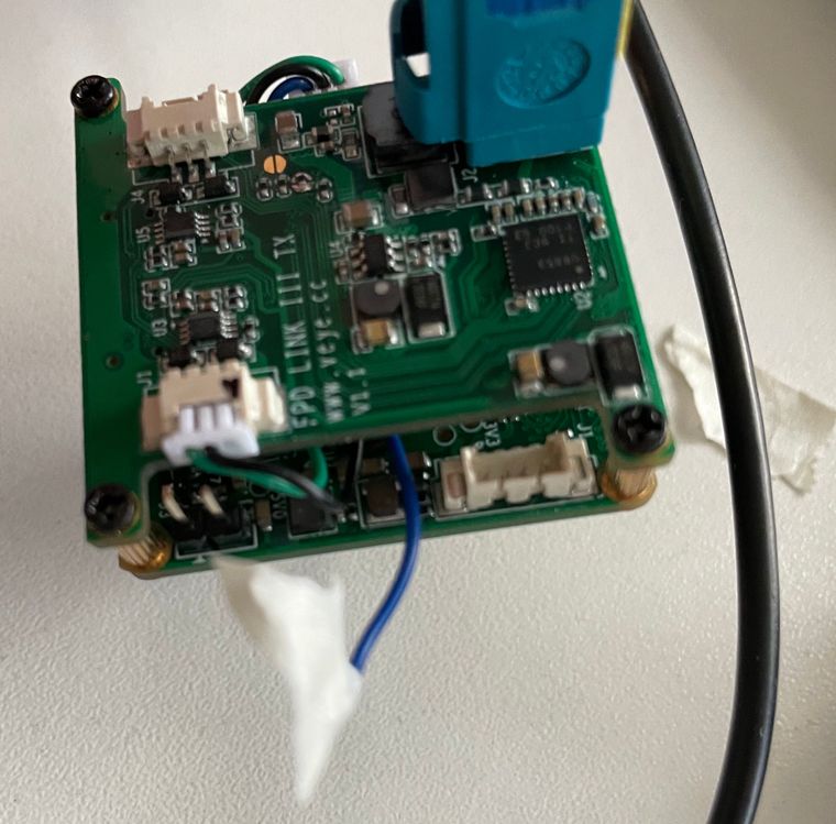
Changed as reference in http://forum.veye.cc/topic/22/i-want-to-synchronize-the-two-cameras-in-sync-mode/6?_=1616485571342
Can you please check what i am doing wrong or post a detailed photo of the right configuration.
Thank you -
@g-towboat
I think you pick out the wrong wire. -
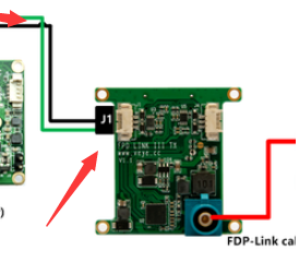
@veye_xumm
SYNC signal connect:
J7-3 (GPIO0) to J1-3 (GPIO0),
J7-2 (GND) to J1-2 (GND)Do i need to do the wireing on each camera? or just master camera.
Any other wiring to do? -
@g-towboat said in Camera sync mode:
@veye_xumm
SYNC signal connect:
J7-3 (GPIO0) to J1-3 (GPIO0),
J7-2 (GND) to J1-2 (GND)Do i need to do the wireing on each camera? or just master camera.
everyone
Any other wiring to do?
no
-
@veye_xumm
It just work with two cameras but not with 8.
Any other ideas whats wrong ? -
@g-towboat
pls check you setting following :http://wiki.veye.cc/index.php/FPD_LINK_III_for_Jetson -
@veye_xumm Hi Xumm,
I use this script to set sync_mode and master slave config:
#!/bin/bash

SYNC_INIT="sync_init"
STREAM_MODE="streammode"

echo -e "connected cameras:"
ls -l /dev/video*

echo -e "Set camera 0_1 to Master"
sh ./fpdlink3_i2c_jetson.sh -f $SYNC_INIT -p 0 -p1 0 -b 30
sh ./cs_mipi_i2c.sh -w -f $STREAM_MODE -p1 1 -p2 0 -b 30 -d 0x3b
echo -e "Set camera 0_2 to slave"
sh ./fpdlink3_i2c_jetson.sh -f $SYNC_INIT -p 1 -p1 1 -b 30
sh ./cs_mipi_i2c.sh -w -f $STREAM_MODE -p1 1 -p2 1 -b 30 -d 0x3c
echo -e "Set camera 1_1 to slave"
sh ./fpdlink3_i2c_jetson.sh -f $SYNC_INIT -p 0 -p1 1 -b 31
sh ./cs_mipi_i2c.sh -w -f $STREAM_MODE -p1 1 -p2 1 -b 31 -d 0x3b
echo -e "Set camera 1_2 to slave"
sh ./fpdlink3_i2c_jetson.sh -f $SYNC_INIT -p 1 -p1 1 -b 31
sh ./cs_mipi_i2c.sh -w -f $STREAM_MODE -p1 1 -p2 1 -b 31 -d 0x3c
echo -e "Set camera 2_1 to slave"
sh ./fpdlink3_i2c_jetson.sh -f $SYNC_INIT -p 0 -p1 1 -b 32
sh ./cs_mipi_i2c.sh -w -f $STREAM_MODE -p1 1 -p2 1 -b 32 -d 0x3b
echo -e "Set camera 2_2 to slave"
sh ./fpdlink3_i2c_jetson.sh -f $SYNC_INIT -p 1 -p1 1 -b 32
sh ./cs_mipi_i2c.sh -w -f $STREAM_MODE -p1 1 -p2 1 -b 32 -d 0x3c
echo -e "Set camera 3_1 to slave"
sh ./fpdlink3_i2c_jetson.sh -f $SYNC_INIT -p 0 -p1 1 -b 33
sh ./cs_mipi_i2c.sh -w -f $STREAM_MODE -p1 1 -p2 1 -b 33 -d 0x3b
echo -e "Set camera 3_2 to slave"
sh ./fpdlink3_i2c_jetson.sh -f $SYNC_INIT -p 1 -p1 1 -b 33
sh ./cs_mipi_i2c.sh -w -f $STREAM_MODE -p1 1 -p2 1 -b 33 -d 0x3c
This is the result:
====== Configure master/slave syncmode ======

connected cameras:
crw-rw----+ 1 root video 81,  0 Mär 29 16:25 /dev/video0
crw-rw----+ 1 root video 81,  3 Mär 29 16:25 /dev/video1
crw-rw----+ 1 root video 81,  6 Mär 29 16:25 /dev/video2
crw-rw----+ 1 root video 81,  9 Mär 29 16:25 /dev/video3
crw-rw----+ 1 root video 81, 12 Mär 29 16:25 /dev/video4
crw-rw----+ 1 root video 81, 15 Mär 29 16:25 /dev/video5
crw-rw----+ 1 root video 81, 18 Mär 29 16:25 /dev/video6
crw-rw----+ 1 root video 81, 21 Mär 29 16:25 /dev/video7
Set camera 0_1 to Master
usage: p1, role,0 is master,1 is slave
init fpdlink sync mode port 0 role as MASTER!
w stream mode master
w streammode 0x 1 slave mode 0x 0 and save param
w paramsave,all param will write to flash
Set camera 0_2 to slave
usage: p1, role,0 is master,1 is slave
init fpdlink sync mode port 1 role as SLAVE!
w stream mode slave
w streammode 0x 1 slave mode 0x 1 and save param
w paramsave,all param will write to flash
Set camera 1_1 to slave
usage: p1, role,0 is master,1 is slave
init fpdlink sync mode port 0 role as SLAVE!
w stream mode slave
w streammode 0x 1 slave mode 0x 1 and save param
w paramsave,all param will write to flash
Set camera 1_2 to slave
usage: p1, role,0 is master,1 is slave
init fpdlink sync mode port 1 role as SLAVE!
w stream mode slave
w streammode 0x 1 slave mode 0x 1 and save param
w paramsave,all param will write to flash
Set camera 2_1 to slave
usage: p1, role,0 is master,1 is slave
init fpdlink sync mode port 0 role as SLAVE!
w stream mode slave
w streammode 0x 1 slave mode 0x 1 and save param
w paramsave,all param will write to flash
Set camera 2_2 to slave
usage: p1, role,0 is master,1 is slave
init fpdlink sync mode port 1 role as SLAVE!
w stream mode slave
w streammode 0x 1 slave mode 0x 1 and save param
w paramsave,all param will write to flash
Set camera 3_1 to slave
usage: p1, role,0 is master,1 is slave
init fpdlink sync mode port 0 role as SLAVE!
w stream mode slave
w streammode 0x 1 slave mode 0x 1 and save param
w paramsave,all param will write to flash
Set camera 3_2 to slave
usage: p1, role,0 is master,1 is slave
init fpdlink sync mode port 1 role as SLAVE!
w stream mode slave
w streammode 0x 1 slave mode 0x 1 and save param
w paramsave,all param will write to flash
Looks good for me.
If i ask the i2c bus which mode is configured, i get this:
Camera 0_1
r streammode 0x 1 slave mode is 0
Camera 0_2
r streammode 0x 1 slave mode is 1
Camera 1_1
r streammode 0x 1 slave mode is 1
Camera 1_2
r streammode 0x 1 slave mode is 1
Camera 2_1
r streammode 0x 1 slave mode is 1
Camera 2_2
r streammode 0x 1 slave mode is 1
Camera 3_1
r streammode 0x 1 slave mode is 1
Camera 3_2
r streammode 0x 1 slave mode is 1
To grab images i use my v4l2-ctl script:
#!/bin/bash

cameras=7
counter=0
while [ $counter -le $cameras ]
do
	echo -e "Camera_"$counter
	v4l2-ctl --device /dev/video$counter --stream-mmap --stream-to=frame_$counter.raw --stream-count=1
	convert -size 1920x1080 -depth 16 uyvy:frame_$counter.raw frame_$counter.png
	((counter++))
done
Camera 1 images looks good.
some cameras a purple some are blue!
Do you need more informations? Or do you have any ideas whats wrong?
-
@g-towboat said in Camera sync mode:
some cameras a purple some are blue!

Do you need more informations? Or do you have any ideas whats wrong?which one is purple,which one is blue?
I think the script is good. It might be wire connection problem.
Could you draw a sketch of this part? let me have a look. -
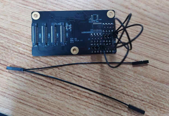
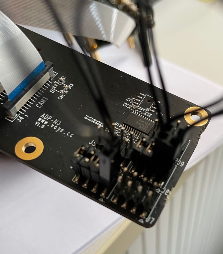
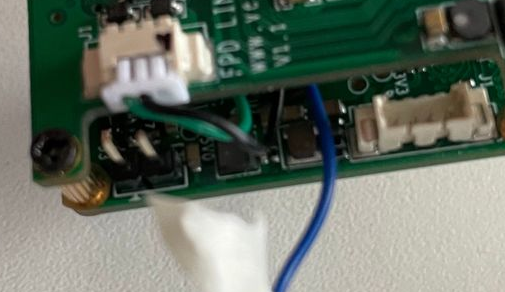
@veye_xumm
Hi here is my drawing: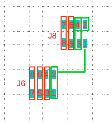
Red: the jumpers
Green: the two black delivered wiresFollowing cameras showing this kind of image:
Camera 1 /dev/video0 image ok
Camera 2 /dev/video1 blue image
Camera 3 /dev/video2 purple image
Camera 4 /dev/video3 image ok
Camera 5 /dev/video4 purple image
Camera 6 /dev/video5 blue image
Camera 7 /dev/video6 purple image
Camera 8 /dev/video7 blue image -
@g-towboat
I think your wire connection is ok. Do you install a lens on your camera?
I don't understand the purple image.
Please post a purple image and a blue image. let me look at it.
Hello! It looks like you're interested in this conversation, but you don't have an account yet.
Getting fed up of having to scroll through the same posts each visit? When you register for an account, you'll always come back to exactly where you were before, and choose to be notified of new replies (either via email, or push notification). You'll also be able to save bookmarks and upvote posts to show your appreciation to other community members.
With your input, this post could be even better 💗
Register Login